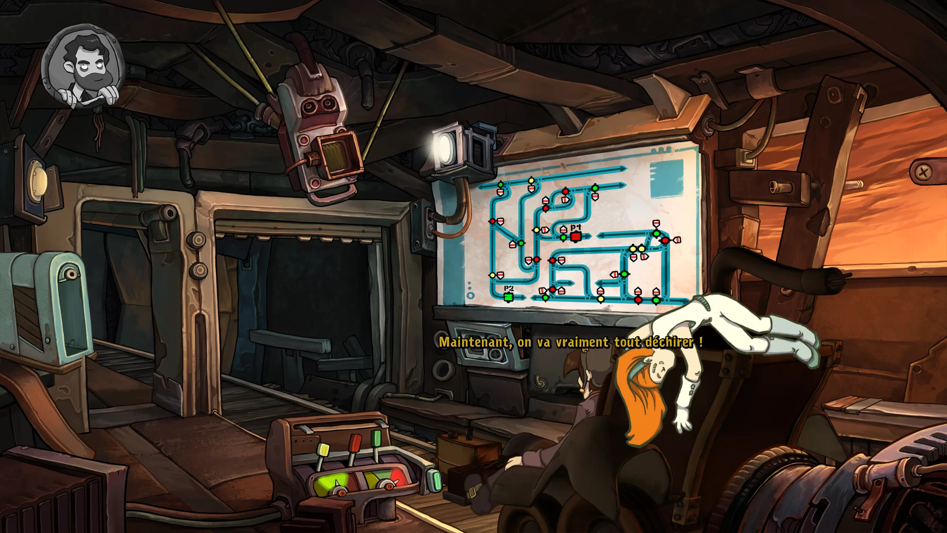
Do you know Deponia ? A well-known point'n click game, i found myself enjoying a lot.
What is of interest here is that this game sometimes offers «minigames», as they are called by the dev. eg some puzzles integrated into the game universe, with their own logic. They need to be solved for the player to progress in the game.
One of them interested me a lot, because it's a very good exercise of problem modeling with graph theory.
It's exactly the goal of that article: model the problem, and implement a method to solve it. (as a consequence, this will spoil one of the puzzle of the game ; but since this game as a gargantuan amount of them, and that this one is one of the simplest and do not unveil anything of the story, you will not be spoiled much if you didn't play it already.)
Obviously, given the time needed to write this article (initially in french), make the code and the images, i could have instead brute force the puzzle more than 100 times.
But that is for the science.
prerequisites
Graph theory : know what a directed graph is is enough to understand the model.
For an introduction to graph theory, look up here in video (french) (or search for any introduction to graph theory), or the wikipedia page for text.
I will also use Answer Set Programming (ASP), more precisely clingo, Potassco Labs' implementation. A big tutorial (in french) is on the way,
but it's not absolutely necessary. I have annotated a lot the few source codes, the important is really what happen around them, not inside.
The situation
levers
This is the situation :
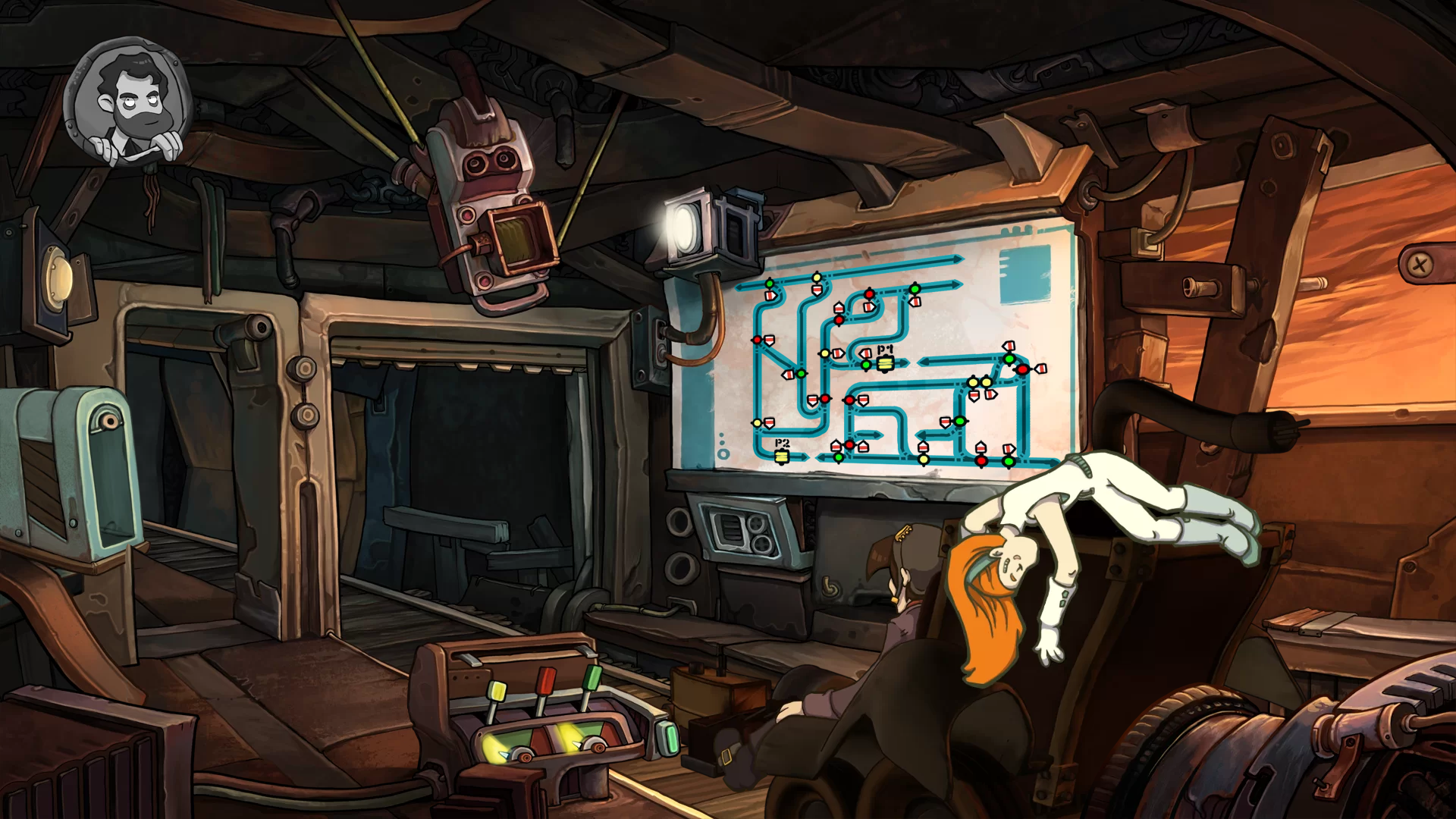
Our character, sitting on its mines dragster/trolley (and accompanied by another character, taking a nap, more or less), wants to pass through montains. Mines are a real maze, but fortunately, there is a plan of the railway network !
Here is it, bigger, when we can see the forks/points, each time colored in green, red or yellow, along with an arrow indicating which direction will be took by the trolley. We start on the upper left, and the goal is to go to the lower right.
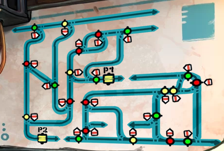
The player may act on three levers, one for each color, to modify the points of the said color. Since there is two possible paths for each fork, the lever has two possible positions. Difficuly comes from the global changing of all forks of the given color with one lever state change.
gates
The second difficulty comes from gates, named P1 and P2. When the trolley go over one of them, the forks of a given color change their state, as if the lever state was changed. Each gate is associated with one color, and by default both are associated to yellow.
determinism
Small important detail : the puzzle is deterministic. That means that if i try two times the same configuration, the trolley will follow the exact same path, and i will end up with the exact same outcome.
the enigma
We can formulate the enigma as follow : knowing that i can choose states of the three levers and color associated to each gate, and that these last can change le levers states during the test of the solution, which initial configuration should i choose to reach the goal, i.e. the lower right, on the other end of the mine ?
Configurations arithmetic
A configuration is five things:
- state of the red color (1 or 2)
- state of the green color (1 or 2)
- state of the yellow color (1 or 2)
- color of gate 1 (red, yellow or green)
- color of gate 2 (red, yellow or green)
There is therefore 2 * 2 * 2 * 3 * 3 = 8 * 9 = 72 different initial configurations available to the player.
We can note that it's a small amount. With 20 seconds to test a configuration, we would need in the worse case less than a half-hour to brute force the problem.
configuration description
Let's agree on a writing convention. A configuration will be written for instance 122JR, to describe a configuration
where red forks/points are in state 1, the yellow ones at 2, the green ones at 2, the first gate in yellow and the second gate in red.
When gate colors will not have any importance, i will just write down the three first figures.
The default configuration, shown in game screenshots, is 111JJ.
The player is free to modify this configuration with different buttons, and to test it, and retry until success. He can't modify it during the mine walk by the trolley,
so the initial configuration is the only thing that determine the outcome (success (pass to next chapter), or loose (try again)).
Simple modelisation
Graph theory is awesome [[citation needed]], and for that precise problem, it's the perfect tool.
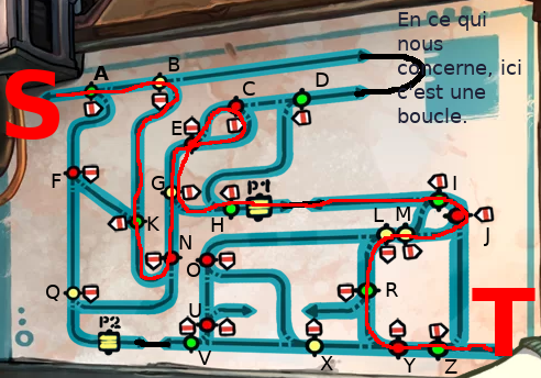
First thing first, let's give a name to all forks (we keep P1 and P2 for the gates), and to the start (S) and the end (T):
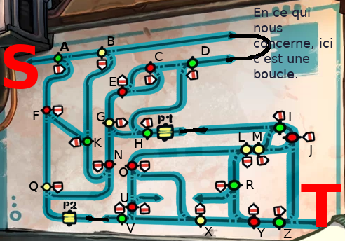
Now we can observ an interesting property of the graph: if a take for instance the point A, and i say i come to it by the left. Question : where will i going next ? This can be partially answered by : if green points (such A) are in state 1, then the trolley will go to point B. And what will happen next will depends solely of the configuration and B itself. If on the other hand, the green forks are in state 2, the trolley will go down to the point F Again, the remaining trip will entirely depends on F and the configuration.
In short, mines exploration is deterministic, and depends only of two things : next fork and the current configuration.
(note that when a fork is taken «in reverse», e.g. fork C when the trolley comes from D, it do not influence the trolley move. In the precise case of a trolley going to C from D, the next point it will encounter is, as far we are concerned, G)
Modeling with a directed graph
Now we have names for the objects of the puzzle, we can modelize the plan as a graph where :
- nodes are forks of the plan.
- edges are directed, linking a fork to the next to be encountered.
For instance, in our graph, the node A symbolizing the point A will be linked to two other nodes, B and F. We also add two special nodes : the start point as S, and the terminal goal, T. To conserve information about the fork choice based on colors, we will also:
- keep color on the nodes. The node is therefore green, because the fork A is green.
- give a weight to edges, with a value of 1 or 2. Each node will therefore have two output edges, one weighted «1», which will link to the next node to reach when the configuration indicate 1 for the node coler, and another weighted «2», which will be the other path used when configuration for the node color is 2. For instance, the arc going from A to B will be weighted with 1, because by default the fork A goes to B. Similarly, the edge going from A to F will be weighted with 2.
Note that with this solution, we do not have to think about the direction in which a fork is encountered : actually, a fork took «in reverse» is ignored in the model. That's a lost information, but a useless one, regarding the puzzle modeling and solving.
Gates management
Gates complexify the model a little. The naïve solution consist to give a node for each, but it do not work because their behavior is asymetric . If i say «i'm coming on P1, where do i go next ?», you can't answer, because there is two possibilities : H or J. In short, it depends if you pass through them by the right or the left.
With the naïve solution, we have to keep in memory from where we come from, and allow a node to act depending on that. This would belong to the configuration, and to me it's an awful way to go, if you want my take on it.
The very standard solution to that class of problem is to get, not one, but TWO nodes for a gate.
For instance, for gate P1, we can call them P1L (L for left) and P1R (R for right). Now, we can enounce the following property:
- when a fork goes on P1 by the right, the associated node will be linked to P1D.
- same with left and P1G.
- we link P1D with the fork met when we quit the P1 by the left, with two edges weighted with «1» and «2», because a gate has only one destination in a given direction.
- same with P1G.
With that solution, everything becomes simple : we can for instance put two edges weighted «1» and «2» from P1D to H, because when we go to P1 by the right, we in any case go to H after.
Note that this do not handle the side-effect of gates: they change the configuration. This is not managed by our model, but we will see how to handle it… step by step.
Example of final model
This is an example with only the edges going from A, B, D and F:
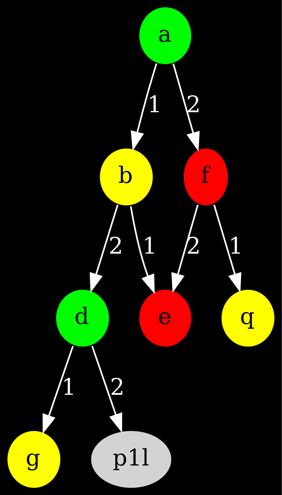
Go ahead, verifiy by looking on the plan. Will we have the real graph ? Sure, but we first have to… retrieve it.
Data retrieving
(and a story-time pause)
This is the boring part (for me): retrieve and encode the graph corresponding to the game plan.
I could have generated one by myself, and use it instead of the game plan. That would have prevent me a half-hour copy work on an annotated screenshot (remember, that's the time needed to brute force the puzzle ?). But, you see, game's instance has a big interest : it was designed to be interesting.
Yes. If i generate a graph without working on it much, there will probably be no solution. Or a trivial one. Or too hard to find for humans (because, since we're at it, let's generate a graph with 1 millions forks and 100 different colors. Game's lifespan will raise considerably). Or cycles that make it impossible to finish.
Interesting anecdote : the game designer (his comments are accessible in-game) explains about this precise minigame that an horrible bug happened sometimes if first game versions… The trolley would never end its journey ; it reached a cycle. On a generated graph, that problem would happen often : you just need that a fork lead to itself, with the same configuration. The dev then relate the hard time he had fixing the plan, until being sure to 100% there is no cycle, and that the graph is still interesting to explore. And not too complex.
In short, in that article, we will discover how the said designer could have modelize the problem, and perform an automatic exploration of the solution space to find all cycles problems, and to ensure the existance of solutions.
Raw data
After, one hour of manual data collection and verification, i ended up with ASP encoded data (complete file here):
nodecolor(c,red).  % fork C is red
rel(c,1,s).   % by default, from C we return to the start :(
rel(c,2,g).   % else, we go to G
rel(d,1,g).   % by default, from D we go to G
rel(d,2,p1l). % else, from D we go to the gate 1, by the left
There is other standard info, like node colors, start and end nodes,… Anything that define that problem's instance.
With biseau, we can print the graph as such:
color((a;d;h;i;k;r;v;z),green).
color((b;g;l;m;q;x),yellow).
color((c;e;f;j;n;o;u;y),red).

link(X,Y):- rel(X,_,Y).
dot_property(X,Y,taillabel,L):- rel(X,L,Y).

obj_property(edge,arrow_head,vee).
obj_property(edge,color,white).
obj_property(edge,fontcolor,white).
obj_property(graph,bgcolor,black).
obj_property(graph,dpi,400).
To get the following visual of the Deponia graph:
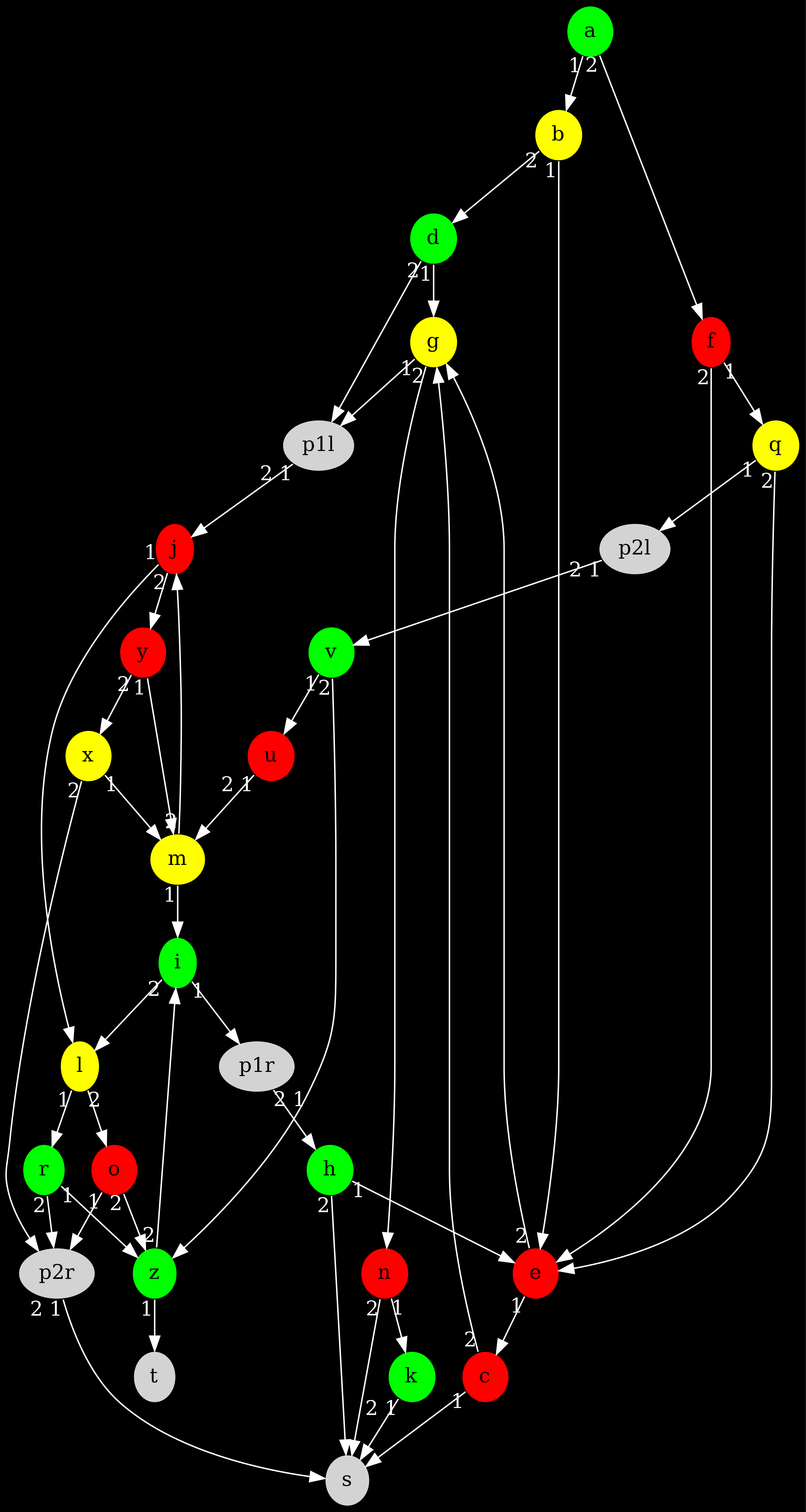
That indicate that we have everything we need to do what we want to. Let's go !
Resolution without gates
As we see, the gate problem is only partially solved: they change the configuration on the fly. That sucks. Boo. Bad Gates.
Well, in reality there is many ways to handle them. But first, let's ask ourselves : is there any solution that do not pass by any gate ?
The answer can be easily answered with ASP:
% Search for a solution without using the gates.

% We choose a value (1 or 2) for each color.
1{colorvalue(C,1..2)}1:- nodecolor(_,C).
rjv(R,J,V):- colorvalue(red,R) ; colorvalue(yellow,J) ; colorvalue(green,V).

% The path allows us to follow the performed move in the mine.
%  We start at the start [Obvious et al. 2018].
path(1,Node):- start(Node).
% We go to the node succeding to the last path, according to color values and the color the previous node.
path(N,Succ):- path(N-1,Pred) ; rel(Pred,ColorVal,Succ) ; nodecolor(Pred,Color) ; colorvalue(Color,ColorVal).

% Final state: we reach the end (win), or we got to the start (loss).
game(win,N):- path(N,t).
game(loss,N):- path(N,s).
% Special case: we are «lost», probably stuck in a cycle.
game(lost,(N,E)):- path(N,E) ; not path(N+1,_) ; not final_node(E).

% Outputs
#show.
#show rjv/3.
#show path/2.
#show game/2.
Even if you do not know ASP, you can run the code on the net,
or you can download the binary,
and feed it with the files, e.g. clingo graph.lp no-porte.lp -n 0 (the last arg is to get all the answer sets).
Whatever you choose, here is the solver output:
Answer: 1
path(1,a) rjv(1,1,2) path(2,f) path(3,q) path(4,p2l) game(lost,(4,p2l))
Answer: 2
path(1,a) rjv(2,1,2) path(2,f) path(3,e) path(4,g) path(5,p1l) game(lost,(5,p1l))
Answer: 3
path(1,a) rjv(2,1,1) path(2,b) path(3,e) path(4,g) path(5,p1l) game(lost,(5,p1l))
Answer: 4
path(1,a) rjv(1,1,1) path(2,b) path(3,e) path(4,c) path(5,s) game(loss,5)
Answer: 5
path(1,a) rjv(2,2,1) path(2,b) path(3,d) path(4,g) path(5,n) path(6,s) game(loss,6)
Answer: 6
path(1,a) rjv(2,2,2) path(2,f) path(3,e) path(4,g) path(5,n) path(6,s) game(loss,6)
Answer: 7
path(1,a) rjv(1,2,2) path(2,f) path(3,q) path(4,e) path(5,c) path(6,s) game(loss,6)
Answer: 8
path(1,a) rjv(1,2,1) path(2,b) path(3,d) path(4,g) path(5,n) path(6,s) game(loss,6)
SATISFIABLE

Models       : 8
Calls        : 1
Time         : 0.001s (Solving: 0.00s 1st Model: 0.00s Unsat: 0.00s)
CPU Time     : 0.000s
We see 8 answer sets, numbered from 1 to 8. It's what we expected, since there is 8 combinations of configurations in our case (2 states for each 3 colors). The configuration is given by atom rjv/3.
Now, we can understand the meaning of over atoms :
path(N,F): at step N, we are on fork F. We can see we always start at A, and then we go to F or B, according to the configuration value for the green forks.game(lost,(N,F)): we are lost/stuck at step N, on fork F. This is not possible in the enigma (thanks to the dev's hard work), but since we currently ignore the gates and stop at them, it is possible.game(loss,N): at N-th step, we arrive to the start node. That mean the configuration is not valid.game(win,N): at N-th step, we arrive to the end node. That mean we succeed. And no, none answer set provides this atom.
With this little experiment, we can gain some intel about the problem:
- first, we are forced to pass by gates to find the goal. So the solution involve use of gates.
- configurations 111, 221, 222, 122 and 121 are waste of time : they will return to the start, whatever the gates configuration is.
Just with few lines of code, we can reduce the space search. There is no longer 72 configurations to test… but only 27.
Anecdote : configuration 111 is both the starting configuration in the game, and the one that end in the minimal number of step. Coìncidence ?
Complete modeling with dynamical state
We got it : without the gates, no solutions. To who's idea to implement only a half of the puzzle ?
To manage the doors, a very simple solution consist into look at the states of forks as dynamic, i.e. changing like the step number (first arg of path/2 atoms in the previous section).
Here is dy-porte.lp, an implementation who use atoms path/3 to encode paths (the code grows in complexity):
% Search for a solution with the color configuration as dynamical state.

% To avoid an infinit loop in case of cycle, we got a maximal number of step.
#const path_maxlen=100.  % big engouh for this instance

% One initial value for each color.
1{colorvalue(C,1..2)}1:- color(_,C).
rjv(R,J,V):- colorvalue(red,R) ; colorvalue(yellow,J) ; colorvalue(green,V).
% One color for each gate.
1{gatecolor(Num,(red;yellow;green))}1:- gate(Num,_).

% The path/3 atoms defines the path followed by the trolley in the mine.
%  Start at start, with initial configuration.
path(1,Node,rjv(R,J,V)):- start(Node) ; rjv(R,J,V).
% Find the next node based on the current configuration and the previous node. Configuration do not change.
path(N,Succ,RJV):- path(N-1,Pred,RJV) ; rel(Pred,ColorVal,Succ) ; color(Pred,Color) ; define_colorvalue(Color,RJV,ColorVal) ; N<path_maxlen.
% Special case: gates. They change the configuration.
path(N,Succ,rjv(R2,J2,V2)):-
    path(N-1,Pred,rjv(R,J,V)) ; rel(Pred,_,Succ) ; N<path_maxlen ;
    gate(NumGate,Pred) ;  % it's a gate
    gatecolor(NumGate,GateColor) ;  % the RJV change according to gate's color
    define_state(red,GateColor,R,R2) ;  % determine new RJV value.
    define_state(yellow,GateColor,J,J2) ;
    define_state(green,GateColor,V,V2).

% Hard part : define the new state (arg 4) of a given color (arg 1), knowing its current state (arg 3), and the color of the gate (arg 2).
define_state(Color,Color,State,New):-  % Considered color is the same as the gate: the state must change.
    color(_,Color) ; State=1..2 ; New=3-State.
define_state(Color,OtherColor,State,State):-  % color different from the gate: we leave the state unchanged
    color(_,Color) ; color(_,OtherColor) ; Color!=OtherColor ; State=1..2.

% Similarly, define the state to take into account (arg 3), knowing the fork color (arg 1) and the current configuration (arg 2).
define_colorvalue(red,rjv(R,J,V),R):- R=1..2 ; J=1..2 ; V=1..2.
define_colorvalue(yellow,rjv(R,J,V),J):- R=1..2 ; J=1..2 ; V=1..2.
define_colorvalue(green,rjv(R,J,V),V):- R=1..2 ; J=1..2 ; V=1..2.

% Final state: we reach the end (win), or we got to the start (loss), or we got stuck in a cycle (cycle).
game(win,N):- path(N,t,_).
game(loss,N):- path(N,s,_).
game(cycle,N):- path(N,E,_) ; not path(N+1,_) ; not final_node(E).

% We filter out the loss cases: they do not interest us.
%  (We will then only get wins and cycles)
:- game(loss,_).

#show.
#show rjv/3.
#show path/3.
#show game/2.
#show gatecolor/2.
It's a more complex program, because it needs a delicate treatment for the new path/3 argument. For forks, we need to determine which path take according to the configuration received in parameter, not the initial one. For gates, we need to determine the new state for the modified color.
Also, note the presence of path_maxlen, that help us detect an eventual cycle.
Here is the solver output:
Answer: 1
rjv(2,1,1) path(1,a,rjv(2,1,1)) path(2,b,rjv(2,1,1)) path(3,e,rjv(2,1,1)) path(4,g,rjv(2,1,1)) gatecolor(2,red) path(5,p1l,rjv(2,1,1)) gatecolor(1,red) path(6,j,rjv(1,1,1)) path(7,l,rjv(1,1,1)) path(8,r,rjv(1,1,1)) path(9,z,rjv(1,1,1)) path(10,t,rjv(1,1,1)) game(win,10)
Answer: 2
rjv(2,1,1) path(1,a,rjv(2,1,1)) path(2,b,rjv(2,1,1)) path(3,e,rjv(2,1,1)) path(4,g,rjv(2,1,1)) gatecolor(2,green) path(5,p1l,rjv(2,1,1)) gatecolor(1,red) path(6,j,rjv(1,1,1)) path(7,l,rjv(1,1,1)) path(8,r,rjv(1,1,1)) path(9,z,rjv(1,1,1)) path(10,t,rjv(1,1,1)) game(win,10)
Answer: 3
rjv(2,1,1) path(1,a,rjv(2,1,1)) path(2,b,rjv(2,1,1)) path(3,e,rjv(2,1,1)) path(4,g,rjv(2,1,1)) gatecolor(2,yellow) path(5,p1l,rjv(2,1,1)) gatecolor(1,red) path(6,j,rjv(1,1,1)) path(7,l,rjv(1,1,1)) path(8,r,rjv(1,1,1)) path(9,z,rjv(1,1,1)) path(10,t,rjv(1,1,1)) game(win,10)
Answer: 4
rjv(1,1,2) path(1,a,rjv(1,1,2)) path(2,f,rjv(1,1,2)) path(3,q,rjv(1,1,2)) path(4,p2l,rjv(1,1,2)) path(5,v,rjv(1,1,1)) gatecolor(2,green) gatecolor(1,red) path(6,u,rjv(1,1,1)) path(7,m,rjv(1,1,1)) path(8,i,rjv(1,1,1)) path(9,p1r,rjv(1,1,1)) path(10,h,rjv(2,1,1)) path(11,e,rjv(2,1,1)) path(12,g,rjv(2,1,1)) path(13,p1l,rjv(2,1,1)) path(14,j,rjv(1,1,1)) path(15,l,rjv(1,1,1)) path(16,r,rjv(1,1,1)) path(17,z,rjv(1,1,1)) path(18,t,rjv(1,1,1)) game(win,18)
SATISFIABLE

Models       : 4
Calls        : 1
Time         : 0.002s (Solving: 0.00s 1st Model: 0.00s Unsat: 0.00s)
CPU Time     : 0.003s
Four ! There is four possible solutions according to our findings ! That's awesome ! I want to test them all !
Let's first verify our work :
Few observations:
- if you delete the constraint avoiding losses to appear, you get 72 answer sets. Maths are so beautiful.
- there is only losses or wins. No cycle. The dev did its job just great !
- the computation time for that problem is very small. When we know well ASP, that sort of program can be written and debugged in few dozens of minutes. ASP, it's an awesome language for prototype, and even beyond.
- we drag a third parameter, the RJV, all along the way with the trolley, that is sometimes modified when we pass through a gate. That's boring, ugly, and it's not even a graph. I love graph.
Re-read again that last sentence, because it will motivate the last part of that article: with our dynamical state, we manage the gate crisis with ease and efficiency. But graphs are so awesome, we want them everywhere, you know ?
Complete Modeling with graph expansion
Is it possible to modelize completely the problem with uniquely a directed graph ? Without global state modified during execution ? Without global state at all ? YES !
The solution is actually standard.
intuition
Let's think a little bit. If we consider an instance of the problem without gate, it means that the initial configuration can't change. In other words, we can't, for a given configuration, pass through some edges. For instance, if the initial configuration fix the green to state 1, then we could remove all the edge weighted with «2» that goes out a green node. This would not change anything to the solution.
Actually, we could, instead of only one graph with all arcs, get a graph for each configuration, with only the edges we can pass through. For instance, the graph for configuration 111 would have the link from A to B, but not the one from A to F. So is the graph for configurations 121, 211 and 221. On the contrary of graphs of configurations 112, 122, 212, and 222.
Consequences are interestings:
- we yield 8 graphs, one for each configuration.
- there is only one outgoing edge per node, since the configuration do not change.
- so there is no need to weight the edges.
- there is one start point for each configuration, and choosing a configuration is equivalent to choose a start point.
- find the solutions of the instance is equivalent to find the starting points that are linked to the terminal node.
The simple fact of having only one choice of propagation on all node is overwhelming ! There is for instance the expanded graph for configuration 111, with only the nodes reachables from the start point or a gate:

Same for configuration 211:

Well, ok, but we do not handle the gates. And they start to bore us with their configuration changes. Except that, we will see this, our model with expanded graph works well, even with gates. We just need 66 other graphs.
Open the gate
A gate lead to the change of configuration, for instance 111JJ to 112JJ. As we just saw, we have a graph for each configuration. Therefore, if we change of configuration… we change of graph !
It's like if the graphs were planets, and the gates were Star Gates the trolley can use to jump from one planet to the other.
For the exemple, there is the path taken by the trolley for the fourth solution found in the previous section:
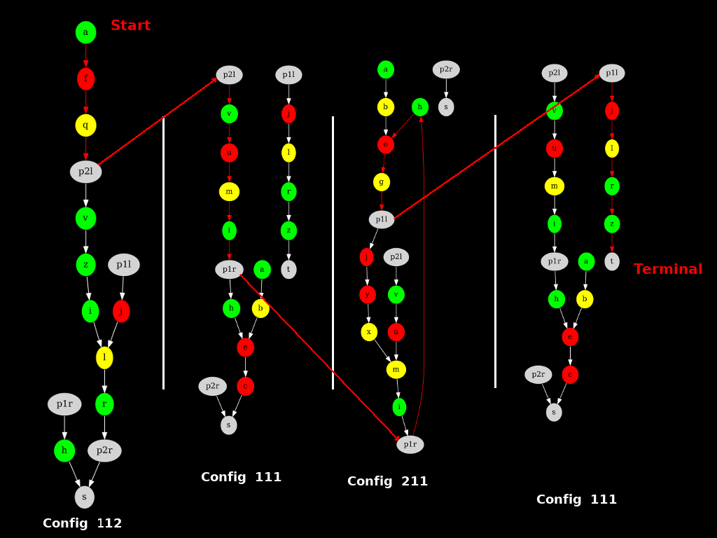
We start at fork A in configuration 111, and we stop at T in configuration 112. In the meantime, as shown by the red-colored path and the solution provided by ASP, we jump from one graph/configuration to another using the Star Gates. Finally, we never encounter a single choice, but we pass through configurations 112, 111, 211 and 111 again.
Note however that here, we only have 4 of the 72 configurations. The total expanded graph is in reality much bigger. Around 18 times larger, to be exact.
Hold the gate
This method is awesome: there is nothing more than a directed graph to handle, and our problem is reduced to a search between starts and the terminal node !
Better ! Do you remember that game in children color books ? Where you have to find a path among others that reach an arbitrary objective (an example here) ?
The universal technic is to, instead of trying each path individually until find the good one (that's brute-force), to start from the end, and climb back up to the start point, which is, by definition, the good one.
Well, we will too apply that thousand year trick : reverse the edges of the expansed graph (A->B becomes B->A), and start from the terminal node instead of the starting nodes. Now, all we have to do is a damn simple graph traversal (a DFS will do, but Dijkstra could provides us the exact parcours and the step amount) to enumerate the nodes we will encounter, and more importantly, those that are starting points.
Thus, there will be two kind of starting points (and therefore configurations, since each of the 72 configurations get its own starting point):
- those that we will find.
- those that we will not be able to reach.
The former are the configurations we wants. It's the configurations that allows us to get to the next chapter of Deponia.
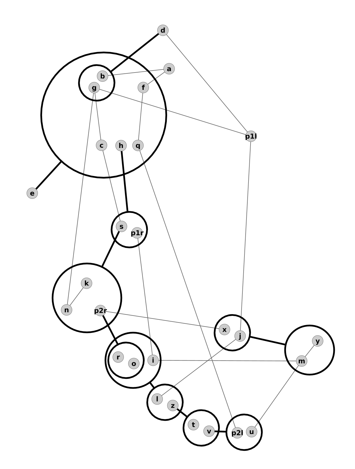
The unique total expanded graph which contains all the configurations is gargantuan. I didn't succeed to load it with dot. Sorry. To make up for this loss, here is a compressed version of the Deponia graph:
Close the gate
This approach, although majestic (because, you know, there is only one graph left), has a notable inconvenience. It's heavy. With the first method, we just drag a global state, very small in memory, and today computers are powerful enough to handle the slight CPU cost it implies.
But with the total expanded graph and its Star Gates, that's another story for memory. It explodes. Add a gate, you end up with 216 configurations instead of 72. Add another, you get to 648 imbricated graphs. With 26 edges per graphs, it's a brand total of 16 868 edges you need to handle. There is only 24 nodes and 52 edges in the initial puzzle.
In short, the thing is growing, and it's growing fast. Exponentially. That could be embarrassing.
Stay positive nonetheless: we have a graph that handle everything. Alone. No more global state, no more special cases for gates !
Conclusions
Why the modeling ?
For the sole instance, i.e. that only puzzle of Deponia, not much.
Except that now, if we ever find another instance or a similar puzzle, we can dig out the whole nine yard, and use standard algorithms to solve it. After all, we just reduce the puzzle to a graph traversal.
Especially as we manage:
- any railway network
- any number of gates (including real Star Gates)
- any number of color
- forks with more than 2 choices (you just need a new weight «3» to handle forks with 3 possibilities)
- multiple terminal and starting points.
- automatic detection of solutions, of non-valid or blocking/cycling configurations
And all of that with pretty graphs. Thats beautiful.
Cost
That project lasts long, because it was mainly article writing. Codes were written in 1h, making the images was much longer (without biseau i would still be on it).
Perspectives
We solved the problem, but there is some questions to be asked.
Proper implementation
That's a lot for the sole instance found in Deponia, but if you're a fan of that class of puzzle… you got the ASP source code, and clingo solver can be embedded into C, lua or python. You don't need to rewrite the solving much.
A simple (but long) thing to do would be a proper implementation with standard input formats to describe the instance to solve, and pretty printing of the infos found on the instances: solutions, cycles,… That program could also perform some puzzle generation:
Puzzle generation
Is it possible to build a program that would generate other instances of the puzzle ? In itself, yes: generate a random graph, with the properties that interest us regarding the node out degrees, and run the ASP codes seen before to determine if:
- there is at least one solution (at least one answer set with «win»)
- there is not too much solutions (not more than few answer sets with «win»)
- there is no reachable cycle (no answer sets with «cycle»)
And to restart, until an «interesting» graph is found. The problem with this approach, it's that we do not know how much time will be necessary to generate one single interesting graph. A lot, probably.
Solution: be able to transform a bad graph into a good one. The important part is to be able to modify the generated graph to remove the cycles, which could be done with simple heuristics, but again without performance guarantee.
Maybe is it possible to formalize exactly the properties of interesting graphs ? Or of a subset of them ? It would be cool to think about that, because there is puzzle auto-generation into the bargain.
Other puzzles
There is loads of other puzzles in Deponia, and also in many other games. Many tasks may be abstracted and treated formally. This one was quite obvious : in the game itself, we can see the drawn graph.
An interesting and funny exercise is to understand the games with mathematics. The first example that comes to mind is pokesciences, where we study up to the influence of an opponent on the future evolution of a pokemon, and also the combat system very well formalized.
The other typical example is EVE online, where most assiduous players for economic/ressource parts are working on complex spreadsheets to manage their productions (the community is known for that «spreadsheet simulator» spirit)..
Without surprise, the lifespan of these games (and the interest we can give them) raises significantly with that kind of approach.
The last words
I pass beyond 12h non-stop on a Deponia's enigma, plus 8 other hours to perfect and translate.
With this, i leave you, i have a mine dragster to configure.
